Fast Reroute In MPLS Traffic EngineeringFast Reroute In MPLS Traffic Engineering
Learn how to use the fast reroute feature to create backup and pre-configured paths in MPLS traffic engineering.
May 16, 2014

My previous articles on Multi-Protocol Label Switching (MPLS) traffic engineering have explained the major use cases for the technology, including bandwidth optimization and meeting SLAs. In this final article, I'll discuss the most common driver for MPLS traffic engineering -- fast reroute.
Before explaining how fast reroute is used in the context of MPLS traffic engineering, you'll need to understand the basics of fast reroute.
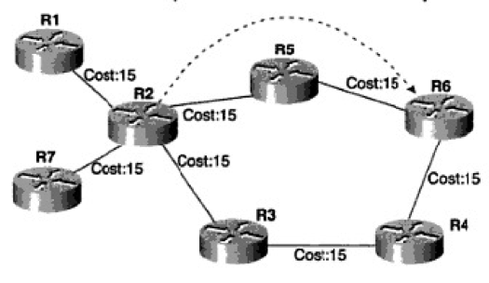
In Figure 1, there are two paths between Router 2 (R2) and Router 6 (R6). If we assume that Open Shortest Path First (OSPF) is used in this topology, then based on end-to-end total link cost, the R2-R5-R6 path would be chosen. The information for the R2-R3-R4-R6 link is also kept in the OSPF link-state database table. If the R2-R5-R6 path fails, the SPF algorithm runs on every router in the same area, and R2 selects R3 as the next hop. It puts this information into the routing table, and if the router supports separated control and data planes, the routing information is distributed into a forwarding information base.
Figure 1: Figure 1
The detection of link failure, the propagation of information to every device in the flooding domain, and calculating and installing the new paths into the routing and forwarding tables of the devices will require some time. Interior gateway protocol parameters for propagation and detection can be changed, and convergence time might be reduced to even less one second. But for some applications like voice, this may not be enough.
We may need latency to be less than 100 or 200 ms in order to reroute traffic without experiencing adverse effects. MPLS traffic engineering can often provide a backup path within 50 ms, because the alternate path is calculated and installed into the routing and forwarding information bases before failure happens.
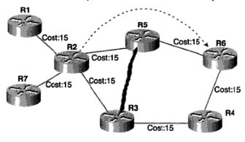
Figure 2: Figure 2
MPLS traffic engineering is a local protection mechanism. There are two modes of local protection: link and node protection. If the R2-R5 link fails and we need to protect that link, we call that link protection. Backup and pre-signaled paths can be created between R2-R3 and R5, so that if the R2-R5 link fails, traffic is automatically redirected to the backup path. Because the failure is local to R2, it is called local protection.
It's also possible for R5 to fail. In this case, the R2-R3-R5 path will not work, so we need to bypass R5 completely. An R2-R3-R4-R6 pre-signaled path could be created for node protection purposes, because in this case, we want to protect the node, rather than the link.
Path protection would come into play if we had the path R1-R2-R5-R6 between R1 and R6 and we wanted to protect that path from end to end.
Creating a Label-Switched Path between all the nodes in the domain might be cumbersome, so automesh and autotunnel features can streamline path creation and protection.
About the Author
You May Also Like


